|
WA8LMF Home Page | Useful Links | Resume ! Updated 25 November 2017 |
Visual Analyser is a freeware Windows application, written by an Italian engineering student, that converts your soundcard into the equivalent of an entire rack of Hewlett-Packet audio test gear. Using both the soundcard inputs and outputs it creates:
With a high-quality sound card such as the Behringer UCA202 external USB sound device reviewed here,
the capabilities of these virtual instruments come very close to the classic hardware versions.' Download this fantastic freeware tool at:
Versions are available for both 32- and 64-bit Windows systems. The application will run on any version of Windows from Windows XP onward.
After downloading and installing the application, starting the program
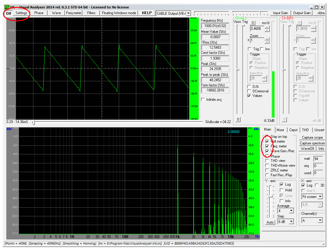
should yield this screen.

Initially the button in the far upper-left corner will be "un-pushed" and show "On" (meaning click to turn on the instruments). Click "Settings" to produce an entire new set of tabs. Then click "Device" to show the dialog for choosing the sound card input and output devices to be used. This dialog can also be used to determine the maximum sample rate and resolution the sound device is capable of. OK the selection and then click the "On" button to start the scope and spectrum analyzer.
You should get a display something like the picture above, depending on your input signals. The spectrum analyzer (lower black window), automatically runs in parallel with the oscilloscope waveform view in the upper black window to produce two views of the same signal.
In the screen cap, Visual Analyzer's own audio generator has been set to create a saw-tooth wave form. A software "virtual cable" was used to loop the generator's audio output back into the audio input for the scope and analyzer to yield the scope and analyzer display. This would be the same as using a 3.5mm-to-3.5mm patch cord to connect the audio output of an actual sound card back into it's own Mic or Line input. With a stereo input sound device , Visual Analyser will function as a dual-trace scope.
(Note that nearly all Mic-In jacks on PC sound systems are monophonic; you must have a device with the "Line-In" third jack, usually colored blue, to use the dual-trace feature.)
The controls for the A & B channels of the scope can be seen in the upper-right corner of the panel. The vertical bar graph indicators shows input in dB, relative to the maximum input level the sound card can handle without clipping distortion. I.e. where the soundcard's analog-to-digital converter maxes out at the largest numerical value it can produce (216 power for the typical "16-bit" sound card).
Any waveform, other than a pure sine wave, contains a series of harmonics (integer multiples of the original a.k.a. "fundamental" frequency). The relative levels of various harmonics depends on the shape of the non-sine waveform. In the screen shot above, the spectrum analyzer is clearly showing the 1KHz fundamental frequency. The 2nd, 3rd, 4th, 5th and beyond harmonics of 1Khz are also clearly visible.
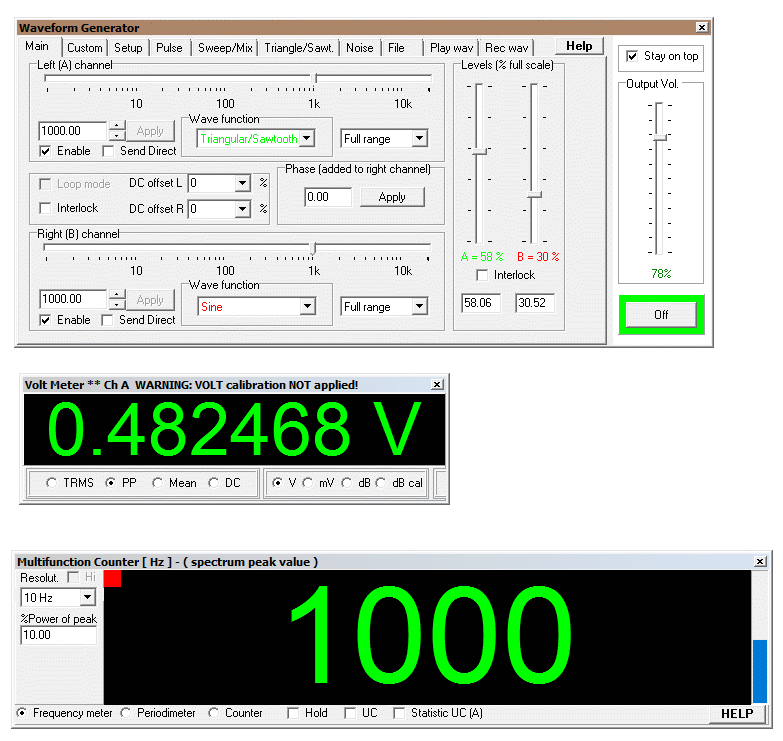
To the right of the spectrum analyzer window, circled in red are checkboxes to turn on and display some of the other instruments. They pop up in free floating windows as shown below.
The top image below is the audio generator. Note that with a stereo output system, you can generate two completely separate outputs at the same time. I.e. you can use the left and right channels independently.
The middle instrument is an audio voltmeter capable of reading either RMS or peak AC levels of signals applied to the sound card. The maximum value that can be read will depend on the input signal handling range of your particular sound card; usually a max of 1 or 2 volts peak-to-peak. DO NOT attempt to look at AC powerline waveforms or similar higher-voltage signals -- your sound card (and possibly the entire PC motherboard) will be vaporized instantly!!!
The bottom window is an audio frequency counter that will display the dominant frequency in an incoming audio signal. This can be used to read sub-audible tone squelch frequencies (a.k.a. "PL" or "CTCSS" tones) for mobile radio systems off-the-air. You will need a wide-band connection to the radio receiver. The radio's discriminator output (sometimes labeled "9600 baud RX") at the 6-pin mini-DIN data port is an ideal point for this kind of measurement. On most radios, the speaker-out jack will not pass enough of these "sub-audible" tones to be read.
[Complete details on the 6-pin Mini-DIN data port, including pin-outs, are here on my website: 6-Pin-MiniDin-Data-Connector ]

This is only a fraction of what Visual Analyser can do. Download this amazing piece of freeware and start playing with it!
