WA8LMF Mirror of WB4APR Website - 21 July 2008
RAFT Docs
 RAFT Chronological Docs and Status
US Naval Academy Satellite Lab, Bob Bruninga, WB4APR
Midshpimen: Robeson and Paquette (06);
Orloff, Kinzbrunner, and Rose(05)
Baker, Tuttle, Colvin (04)
Machinist: Mike Supersczynski
This page is current with the latest status of drawings, documents and efforts.
The main RAFT page is secondary to this page for currency.
Both RAFT and MARScom are at KSC awaiting launch on STS-116 on 5 December 2006.
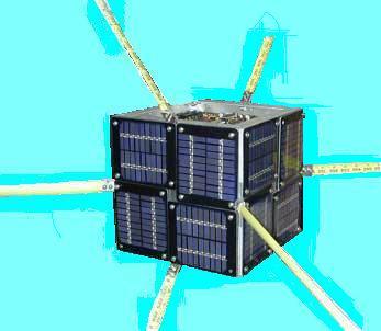
The photo below on 18 Jan 06 shows a completed RAFT1 with GSE test set/equipment
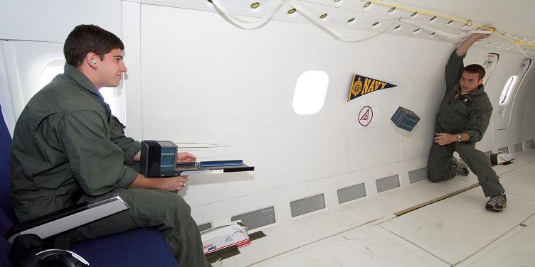
and telemetry screen. The second photo is the 7 April 2006 flight separation test
on the NASA Zero-G flight.


Photos from KSC Integration: 17-21 July 2006
Bob and Perry,
with launcher
Payload Bay Charging GSE,
Charging connections,
Equipment
Final Functional Test 1,
Test 2
In Launcher
Acceptance Data Package and Formal Docs: Delivery to Cape Kennedy - 14 July 2006.
FCC Debris Mitigation Plan
Acceptance Data Package (download)
EXCEL Parts List (download),
Weight and Moments Report (download)
Payload Bay charging plan (download),
Battery Safety Design and Test Report (download)
RAFT Operations Plan (download)
18 May 2006: Completed Thermal-Vacuum and other final tests:
Functional Test Plan(download)
Warnings and Cautions document, including HF winding procedures.
Delivery Item List.
Thermal/Vacuum Test Report download.
RAFT Eclipse Cycle Test to verify RAFT can recover from a dead battery.
MARScom Retuning Report.
7 April 2006: Photos of the Flight Separation test on the Zero-G aircraft:
TRR Readiness,
Test hardware,
Getting ready
Separation,
Catch,
On the rebound,
Reload,
Preps for re-fly,
Long separation,
16 Feb 2006 New Items:
Movie of flight unit separation test.
Also you may Download P-III Safety Presentation

1-3 Feb 2006 JSC Delivery photos:
RAFT Testing:
Test Setup,
Functional Testing,
GSE cables,
RF test.
Launcher Insertion:
Final Torquing,
Winding up HF antenna,
Launcher Insertion,
Launcher Door,
25 Jan 2006 Ship Day photos:
RAFT Closeout:
Top,
Bottom,
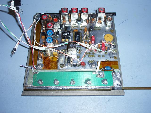
TX & RX,
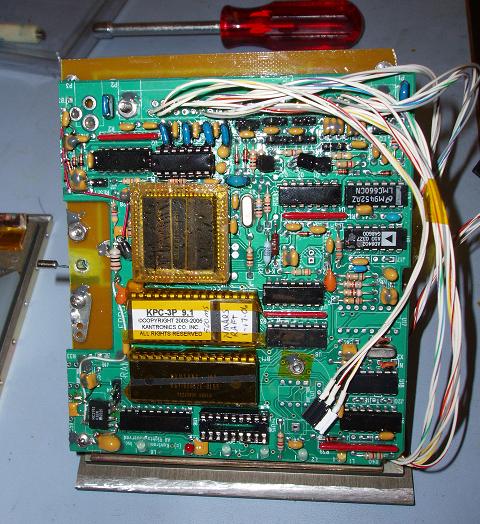
TNC panel,
Top closeout.
MARS Closeout:
Top,
Bottom,
Side,
TNC panel,
RX panel,
Diagonal & Battery panels
VHF SAR rcvr.
18 Jan 2006 Photos:
Solar Panel Testing (group)
Antenna spring assembly (detail)
Diagonal Assembly (IBRD side),
(TNC side),
Interface Board and Voice module.
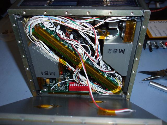
RAFT Bottom View (shows wiring harness)
30 Dec Status: Interim photos for Safety Review. Ballast has not yet been wrapped
in kapton and close-out details and conformal coating has not been done:
Solar Panel Photos:
Top panel,
Side panel,
GSE panel.
Panel inside views: .
Battery panel,
RX panel,
Diagonal panel .
Panel assembly: . . .
Diagonal panel TNC side,
Diagonal panel with 2 battery panels,
Diagonal panel (all sides)
Antenna Views: . . .
Top outside view,
Full view of one antenna,
Top antenna corner close up
19 Dec Status: Completed (95%) circuit integration and testing on RAFT1.
14 Dec was full power up test, with all control circuits working and interfaces
checked out.
TX, RX, TNC, PSK-31 RX, Speech module all OK.
Also GSE software calibrated to telemetry. Command and control checked out and fully functional.
Flight ROM installed and checked out. OK. (minor changes noted)
HF antenna matching design worked out and ready for installation.
VHF antenna matching circuits being wound in Boston to arrive 29 Dec.
Solar panels epoxied process looks great. Panel is fully depressed &
no clearance issues.
Modified PSK-31 turn on circuit for better reliability and no jitter.
New Photos 8 Dec:
PSK-10/Interface board,
(edge view),
B1 Ballast photo,
Ballast/Board clearance.
Flight Hardware Photos: As of 18 Nov, we have completed all 4 VHF antenna
and separation spring assemblies. This photo was taken at about the 50% assembly
point.

See closeup detail
Mechanical Machining Complete: 17 June 05. The following photos show the flight
hardware after anodizing and during fit checks:
Overall Views: All six panels ,
Mating two half-assemblies ,
Outside views: Side Panel ,
Top panel ,
Inside Views: Battery Panels ,
TX and RX side panels .
with RX/TX in place,
STATUS THROUGH 30 Nov 2005:
30 Nov - Full panel fit check complete. Can now do Ballast assessment and looks like lots of room.
29 Nov - Central Diagonal HF antenna / PSK-10 / Control Board / TNC assembly complete
18 Nov - All four VHF antenna and separation spring assemblies complete. Sep force 9.25 LbsF total.
17 Jun - All Mechanical Panels complete, Anodized, All solar panel wiring complete
07 Jun - Electrical and PCB design complete. Flight board on hand. Flight mods to RX and TX complete.
26 Apr - Received all solar panels!
25 Apr - Parts List and
old 23 Feb Material Status Summary
22 April - New springs analysis complete (see Antenna Deployment section below)
25 Mar - HF Antenna deploy test and correction plan
Machine shop fabrication of 12 RAFT side panels has begun with approved overtime.
24 Mar - Batteries in hand. Acceptance Plan submitted 24 Mar.
ELECTRICAL: The items below were grouped together for the Battery Working Group
Meeting held on the morning of 13 Dec 2004. There were no unusual action items as a
result other than the need for a thermal analysis by phase 2.
11 Jan 06: Battery Photos:
Battery Box inside,
Cells in Durette Gold,
Cell ends,
Panel recess and gortex vent
07 Jun 05: RAFT1 Schematics: Schematic,
Test-Set,
Power System,
Solar Panel wiring,
Interface PCB,
Wiring harness.
24 Mar 05: Battery Design:
Box design,
Cold Test plan,
Cold Test Results,
Acceptance Test (word)
09 Feb 06: Safety Plans:
Charge Safety,
Payload Bay Charging Plan,
RF Inhibits Assessment.
15 Feb 06: Safet Tests:
Final Flight RADHAZ test (WORD version),
Battery Cross Charging Test.
18 Nov 04: RAFT1 Express-PCB Printed Circuit Board. (Needs ExpressPCB.EXE to view)
3 Nov 04: Internal Interface Board Layout
 A picture of the mechanical model
MECHANICAL:
19 Feb 05: Design Drawings: . .
Top internal view (rev-L),
Top/bottom Panels,
Side Panel,
Fastners .
28 Dec 05: Assembly Drawings:
Ballast Plan,
Cabling Plan,
Top Panel Anodizing plan,
Side Panel Anodizing plan.
27 Jan 05: Minor Drawings: . . .
Diagonal Bracket,
Sep switch mounting
06 Dec 04: Stress Analysis: . . .
Buckling limit occurs at 10X load factor,
Free Body Diagram with displacements.
19 Nov 04: PDR action item list.
COMMS and TELEMETRY:
08 Jun 05: Circuit Board Mods:
Receiver Mods,
Transmitter Mods,
TNC Mods for telemetry
04 Mar 05: Telemetry Design:
Thermister Curve,
Telemetry sensors and equations
VHF ANTENNAS AND DEPLOYMENT SYSTEM:
16 Dec 05: Antenna T/R switch and matching
29 Dec 05: Spring Separation Dynamics Report
and Combined Spring Separation Forces
21 Nov 05: VHF SWR plot and matching circuit
18 Nov 05: VHF Antenna Assembly photo (closeup)
30 Sep 05: Solar Panel Hole Test showing how we can drill holes with no more impact than area lost.
15 May 05: Two-Spring Dynamics:
Dual spring assemblys,
Lead w/2 springs,
Tail w/2 springs,
2-spring separation.
20 Apr 05: Original Separation Dynamics:
RAFT1 First,
RAFT1 Last;
Lead Satellite,
Tail Satellite,
Separation;
15 Apr 05: Revised Antenna spring assembly and SEP switch,
25 Jan 05: Original
21 Feb 05: Original Plans
Antenna/Separation Plan,
Original Antenna/Spring Lengths,

HF ANTENNA LONG WIRE DEPLOYMENT SYSTEM:
28 Nov 05: HF Mounting Panels: Drawing,
assembled photo,
PSK-10 side photo,
TNC side photo,
Contact pin photo.
28 Nov 05: Magnetic Stabilization attitude for typical western passes (east is mirror image).
25 Nov 05: HF Impedance,
HF Matching Circuit
22 Feb 05: Antenna/Separation Plan (same as VHF dwg above)
23 Feb 05: HF antenna Spool Assembly: drawing,
photo.
MARScom DRAWINGS:
01 Feb 05: Drawings:
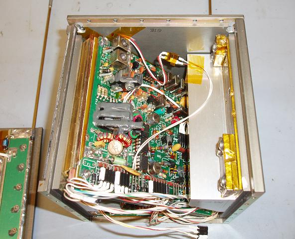
MARScom internal view
UHF Converter Mods (not used).
02 Jun 05: Schematics:
MARS Power System,
MARS Schematics,
Wiring harness .
DESCRIPTIONS AND SKETCHES:
12 Dec 04 Constellation (revised)
19 Nov 04: RAFTs picture (Updated)
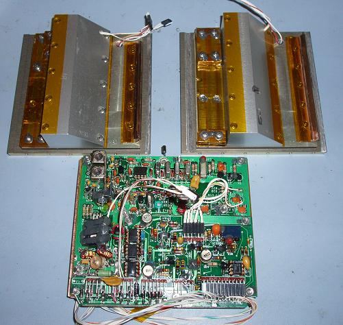
THE 217 MHz NSSS Radar Fence Receiver/Transmitter.
18 Nov XP217 Radar Receiver/Osc Block Diagram
18 Nov Interface Board PCB layout (.GIF file)
15 Nov PCB layout for the 217 MHz NSSS xponder
15 Nov Parts list for 217 MHz NSS Xponder (pdf file)
Other:
13 Dec IARU Frequency Coordination Letter
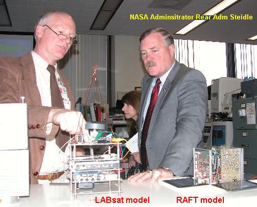
15 Nov NASA Administrator Rear Adm Steidl (ret) views RAFT model(photo)
PRESENTATIONS:
Download Critical Design Review PPT presentation (23 Feb 05)
Download Phase II Safety Review PPT presentation (10 Feb 05)
Download Phase 0/I Safety Review PPT presentation (16 Dec 05)
Download Preliminay Design Review PPT presentation (19 Nov 04)
Download original PPT presentation (April 04)
Completed System Requirement Review (SRR) on 15 Sept 2004 and Safety Kickoff
Meeting. Key issues were:
RAFT has a very Short Schedule for Shuttle SAFETY process (Phase 0/1 review on 30 Nov04)
Extremely tight tolerances on external dimensions (.002") (now looking at +/- .010)
Ejection Requirements solidified as between 24 hours max and 75 minutes minimum prior to USNA AOS
RF and Battery power inhibits (4 required? or N/A due shielding?)
Proposed Inhibit Plan based on 40 dB shielding. See
also a (MS WORD version).
Status: The design is maturing. The new simplified Antenna separation design was demonstrated
and RF shortening of the antennas has been breadboarded with success. The internal design is getting
well fleshed out. See these new drawings since SRR:
Antenna PCB face view for location of crank handle
WA8LMF Mirror of WB4APR Website - 21 July 2008