 US Naval Academy LABsats
US Naval Academy Satellite Lab, Bob Bruninga, WB4APR

US Naval Academy LABsats
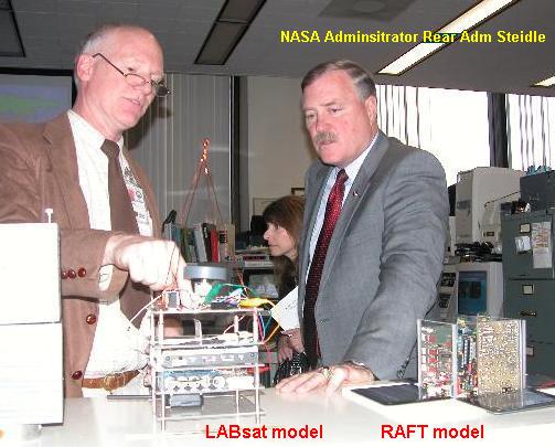
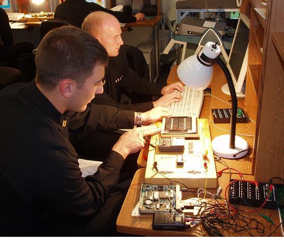
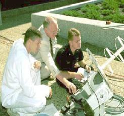
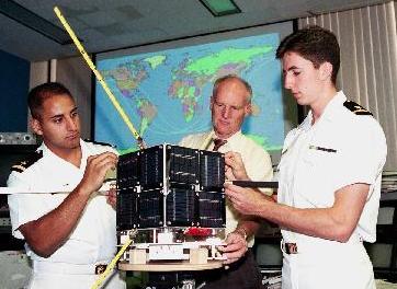
LABsats are incorporated into the US Naval Academy's Aerospace labs to provide various hands-on experiments with satellite technology at low cost. The photo above shows then acting NASA Administrator Admiral Steidle being briefed on the LABsat system we use to support many of our Aerospace labs. We use the LABsats to support a number of space design principles as follows:
EA-467 Spacecraft Design Lab: This web page is just an overview of the LABsats. Students should go to the EA-467 Course web page for the actual LABS and Schedule.
LAB Summary: The labs below are older (non-updated) examples of some of the exercises using these LABsats. Also there is a one-page-per-lab, summary overview(doc) of all the labs as used in 2005. There is also a powerpoint summary of our ground station. For the latest lab versions, visit the student page above. We are also seeking a grant to develop a full lab course series for High Schools and other Universities download. But the following are representative labs:
LABSAT SYSTEM: The LABsat concept was developed at USNA beginning about 1998 to use innexpensive off-the shelf components for under about $600 each ($900 with discrete TX & RX), yet include RF hardware suitable for actually closing the link from orbit in the Amateur Satellite Service. The labsats can not only serve as the final integration of all the modules of the seniors lab course, but they can also serve as rapid prototyping devices for testing modules and components for auxilliary payloads and applications. The Telemetry, Command and Control system communicates at 1200 or 9600 baud using the standard AX.25 packet radio protocol that has flown on MIR, the Shuttle and ISS plus a dozen or more satellites in the Amateur Satellite Service (including 5 of our own). Draft Tech Manual only a draft beginning, much still to be done.
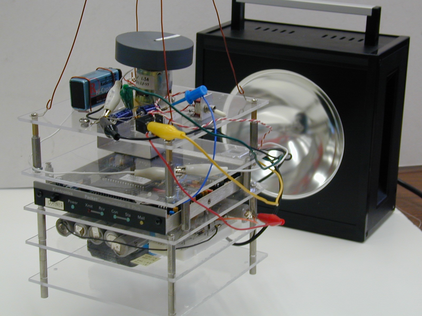
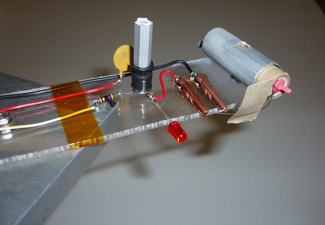
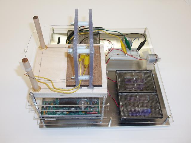
STACKsats: The images above show two typical LABsat stack configurations. These show the momentum wheel and magnetorquing experiments for demonstrating attitude control. The Motor and the orthogonal X and Y torquing coils demonstrate actual attitude control using the Earths magnetic field. When hung from a string, students are able to change the attitude of the labsat, and, with the right pulsing of the coils, spin up or de-spin the spacecraft.
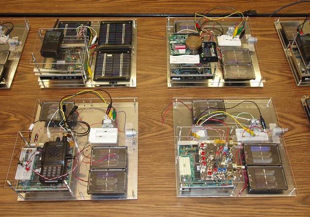
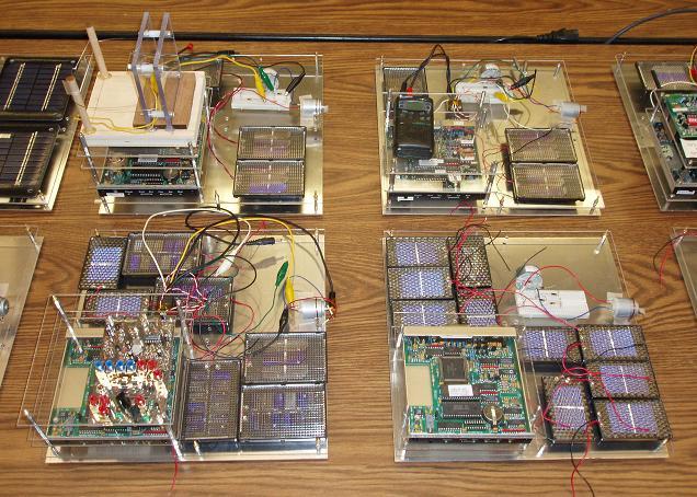
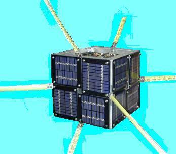
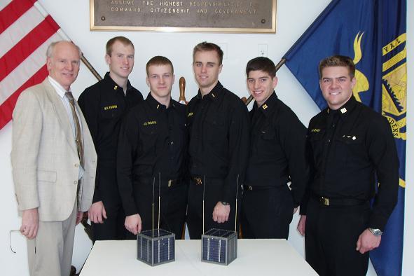
FLATsats: As shown in the 8 different models above, the LABsats can also be configured into a FLATsat configuration for the EPS Solar Panel System design Lab. In the FLATsat configuration, three Solar Panel sides of the spacecraft can be illuminated at once as is the typical illumination of a cube shaped satellite. During the design Lab, we have boxes of 8 different solar cell sub-panels of various voltages and currents. The students must design a power system that can be illuminated under a lamp which will power their LABsat including momentum wheel, while staying within the panel size allocated. Cost is also a parameter of the overall design.
ELECTRICAL POWER SYSTEMS:
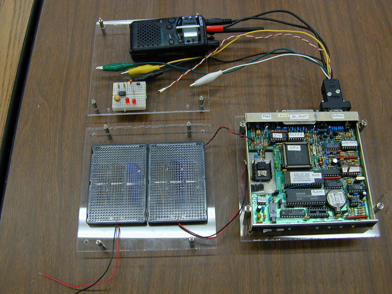
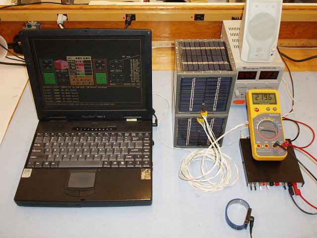
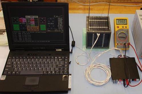
The LABsat is composed of several boards. The image below shows three of the LABsat
boards (the RF Transceiver board, a Solar Panel, and the Comand/Control/Telemetry
board). The single radio transceiver board was replaced with separate TX and
RX boards in 2005 so students could perform individual functionsl tests on these
modules. Other standard boards are the Battery
board, and experimental prototype board. The photo on the right shows how the Telemety
and Transceiver boards are used to make measurements during the Solar Power lab.
The drawing below shows how the LABsat telemetry system is typically used as a data collection device during experiments. In this case the 4 of the channels are being used to collect Solar Panel voltage and temperature, plus current and battery voltage and discharge current of the torque motor.
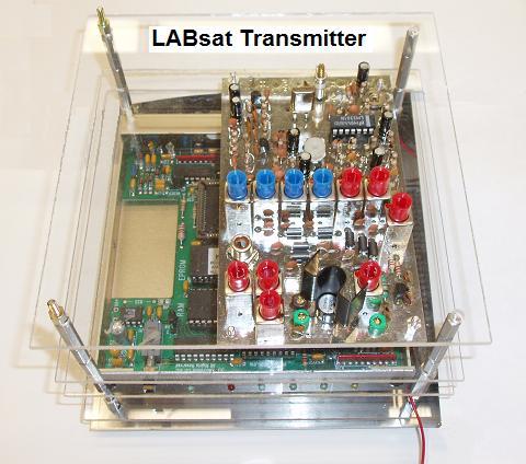
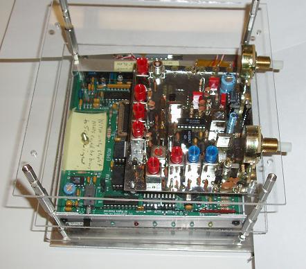
TRANSMITTERS: New in 2005 labs, the original $100 radio transceiver was replaced
with discrete TX and RX panels (at $200 each raising satellite costs to about $900 each)
so that students could measure and
peak the transmitter for peak power out and measure the antenna SWR. They also
observe and measure any harmonics or other spurious emissions. These emissions
are important in passing EMI testing. This experiment also has them plot the
temperature rise of the transmitter final PA amplifier so they learn the heat
involved in a 2W transmitter and how it is mostly concentrated in the final stage
and requires thermal design to get rid of it.
RECEIVERS: On the new discrete receiver, students measure
the 10 dB SNR sensitivity and bandwidth as shown below. They measure the
noise power on the audio voltmeter and then increase the signal until they
achieve 10dB, and then 20 dB SNR. They then move the signal up and down
in frequency to measure the 6 dB bandwidth of the receiver.
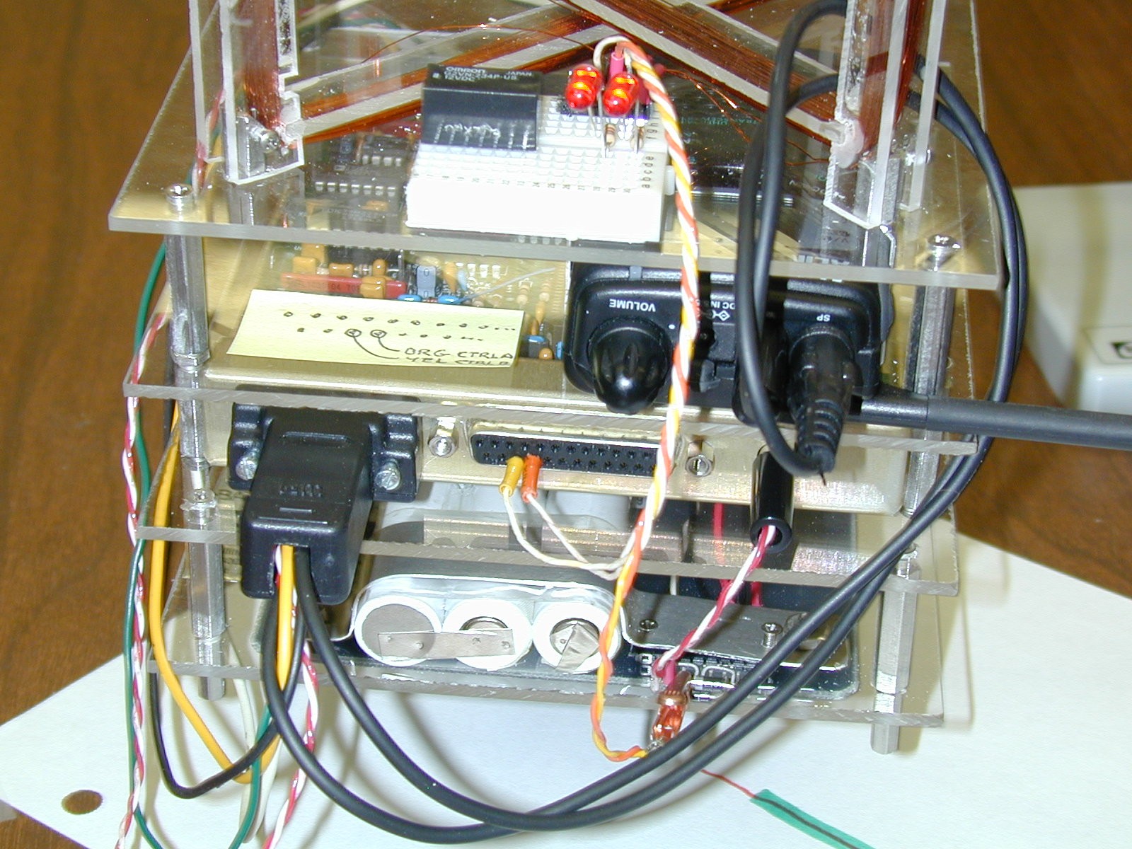
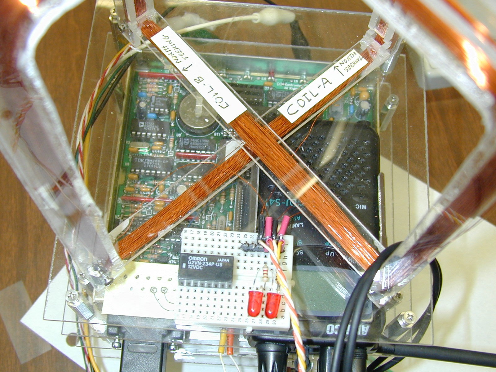
STACK INTEGRATION: The next close up view of the magnetorquing experiment shows how the standard 6"x6" modules stack up to compose a LABsat. By having a common footprint, the students have greater freedom in the physical layout of their designs. In the attitude control lab, they have to arrange for a good center of gravity and calculate their moment of inertia. This view, from top down is composed of:
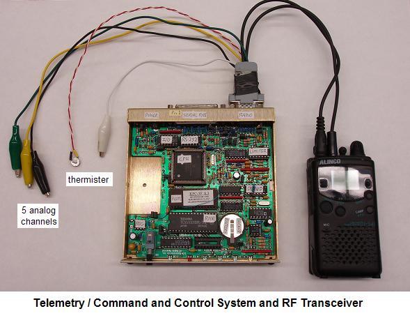
TELEMETRY: The block diagram of the Telemetry Command and control interface is shown below. The bidirectional serial bus allows unlimited expansion to other processors and experiments. This TC&C module is used as the foundation of most of the labsat experiments. It is identical to the 8 currently flown or manefest on USNA satellites.
To prepare the COTS packet modem for use as a Telemetry, Command and Control system, we make modifications to the circuitry and make various taps off of many of the microprocessor I/O lines. With these mods, the students can easily access the CPU telemetry inputs and command outputs. See details of the TNC mods.
LABsat telemetry consists of periodic packets containing a serial number followed by 5 comma delimited analog values in the range of 0 to 255. (see example). This file can be opened directly into EXCEL for display and/or conversion to specific units for display. If more than one LABsat is on the air, then the LSAT-SEP.EXE utility can be run on the combined file sepaarate out each individual labsat's telemetry into its own file for loading into EXCEL. The QBASIC source code is available.
SIGNALS AND MODULATION:
The students use the Transmitters and Receivers and Telemetry system to investigate both FDMA and TDMA systems. They observe and capture time domain waveforms and compare signals on sound-card spectrum analyzers as shown below. The FDMA multi- channel spectrum display is on the left and the TDMA waveform is on the right.
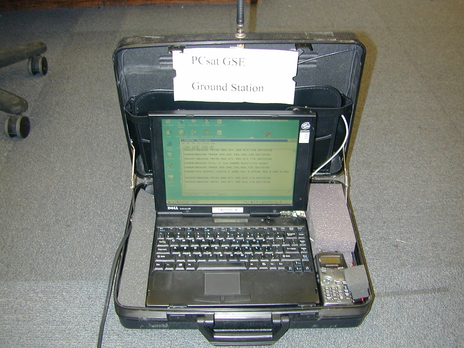
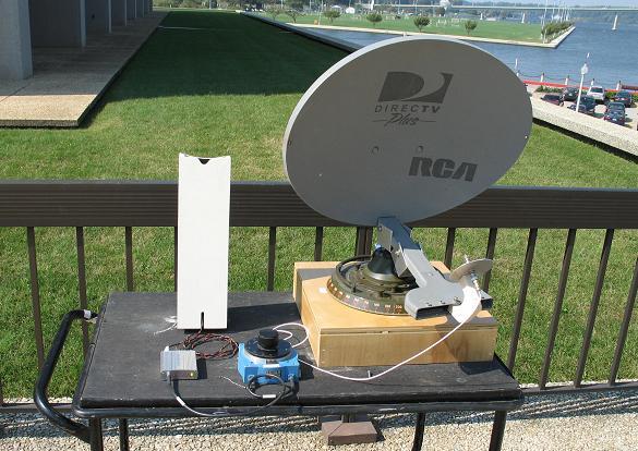
LABSAT GROUND STATIONS: The ground station for both our LABsats and our
USNA Satellites on orbit consists of a brief-case system containing a laptop,
and AX.25 packet radio modem and small radio. The one shown below uses the Kenwood
TH-D7 packet radio that has built-in TNC-modem for easy construction and is
suitable for actual comms with the spacecraft on orbit and in the lab. On the right
is a GSE laptop connected to our flight RAFT and MARScom satellites.
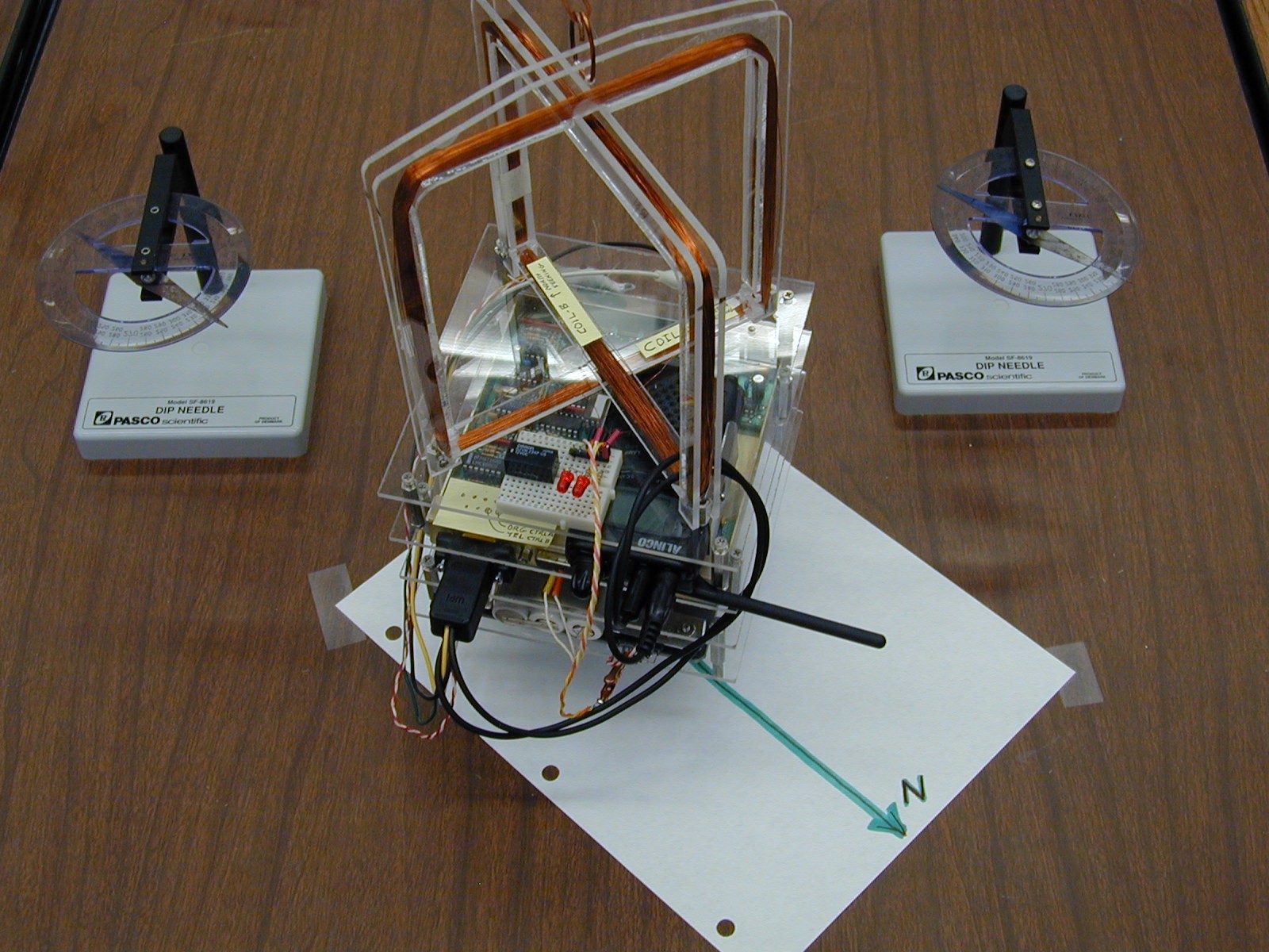
ATTITUDE CONTROL LABS: In addition to the momentum wheel and magnetorquing coils shown above, the attitude control lab also uses a small chemical thruster. The thruster experiment does not use the LABsat electronics at this time, but replaces the electronics stack with a light weight block of foam and a "match-head" thruster as shown below.
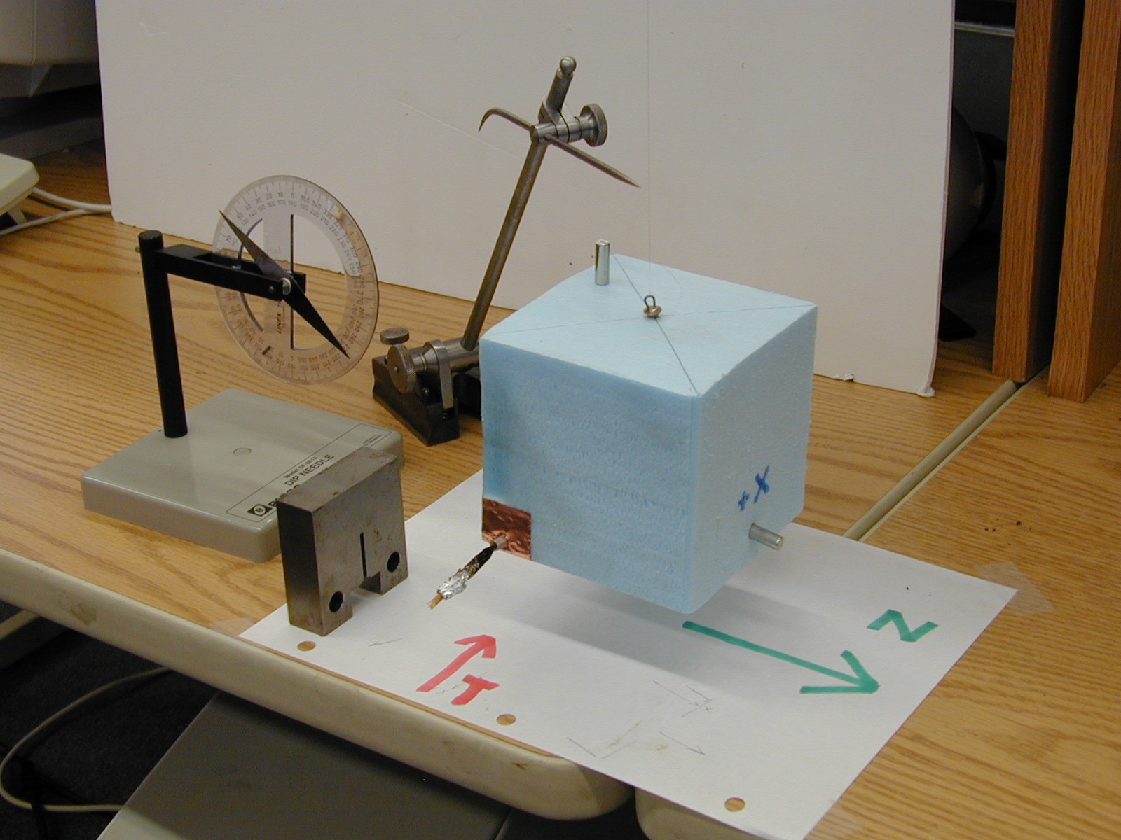
The image shows the foam sat aligned with North (using the small permanent
magnet inserted on the +X face). The Thruster is inserted on the lower left
-Y face and ignited. The moment of inertia is calculated and the resulting
angular velocity is used to calculate the force of the thruster. The dip needle
shows the orientation of the Earths Magnetic field in the lab.
Click for closeup of magnetorquing coils.
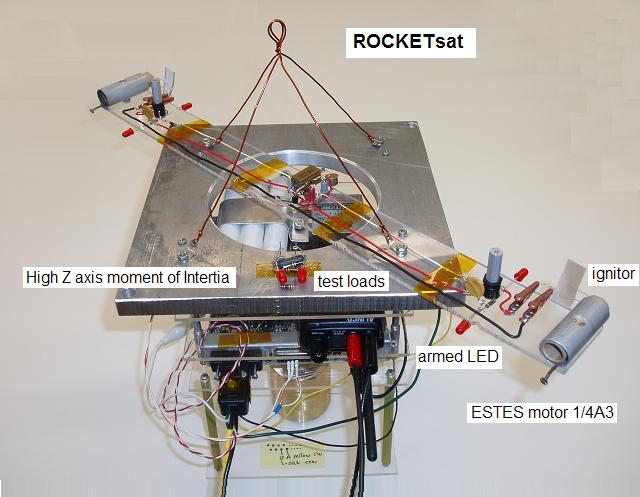
This semester we abandoned the match-motor tiny thrusters for a much more vigorous ESTES rocket motor on an actual LABsat as shown above. This satellite is hung outdoors but close to the lab window so it is easy to see. First the CW motor is fired to give the satellite a good spin. Then the CCW motor is fired and if they are close in performance, then the second motor will counteract the spin and return the satellite to rest in about 1 second.
Magnetic Stabilization: To help studnets visualize the attitudes of spacecraft with magnetic stabilization, I wrote a program to generate many views from our ground station such as the one below. (See more views)
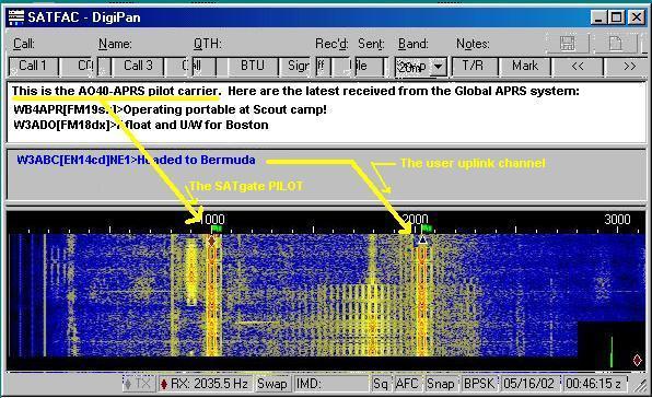
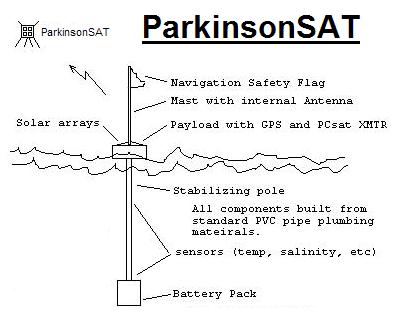
SERIAL DATA COMMUNICATIONS EXPERIMENT: In this lab, the students analyze the serial data output of a GPS unit and connect it to the LABsat command/control system to transmit GPS position data to the ground station. The data is then decoded and displayed on a local map of the Academy. Each GPS (since the experiment is conducted indoors) is pre-loaded with a simulated position. The screen shot below of the APRS display shows the positions reported by their GPS units and the callsigns the students gave their labsats for this experiment. The students are required to manually parse the data fields and then this display gives them feedback about their successful data transmission.
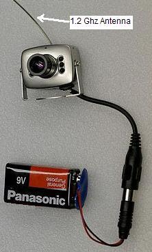
OTHER Experiments: Another advantage of the LABsat based experience for the students is that they can use it as the baseline for building and testing other sub components of their EA-470 satellite design work. In the photo below, a FLATsat model was used to test a string-cutter antenna deployment design for one of the early RAFT models. In this case, the students could concentrate on the mechanical and structural details and simply use the FLATsat as the control system. On the right, students experiment with a UHF helix antenna.
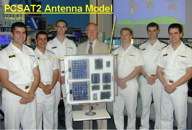
SATELLITE TRACKING: The USNA Satellite Lab maintains a track on all of our own satellites plus other university and interesting satellites. When passes occur during labs, students participate in ground station operations. In a number of experiments, the students have done the planning and scheduling of PCSAT2 and PCSAT1 commanding. (PCSAT2 Ops Lab), (Joint ops Planning Lab). The image below is used to help the students visualize the daily pass geometry of PCSAT2 over our station.
FLIGHT HERITAGE:
The LABsat hardware is derived from the actual flight hardware used on several
of the successful Naval Academy Satellite designs that have flown or are currently
manafest. These systems are similar and compatible to what has flown on the MIR,
ISS and the Space Shuttle for use by schools and universities around the world.
By using a common Telemetry Command and Control system, the independent
flight systems can actually be used in constellation with each other for
multiple satellite experiments. Also, their commonality encourage colaboration
with other schools making similar compatible systems.
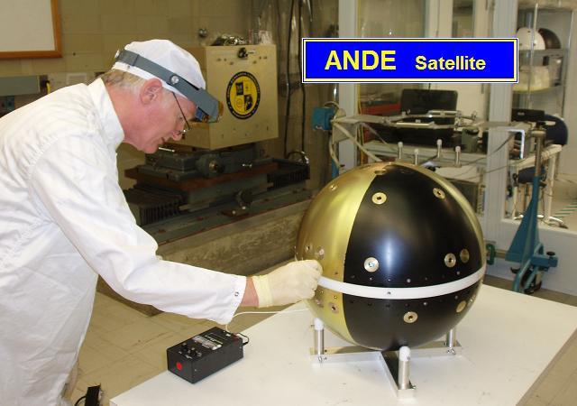
USNA SATELLITES: A total of eight independent Telemetry Command and Control Systems similar to our labsats have flown or have been delivered for flight as shown below. Both PCsat, PCSAT2 and ANDE are dual systems, meaning they carry two complete systems each. The dual systems give redundancy, and also give multiple functionality. The RAFT and MARScom systems have single TC&C systems.
LABsat Drawings: Here are some of the documents that describe the LABsat details. These are not all inclusive, but are all that we have posted at this time...
You are visitor:
since 1 Dec 2004.
|
|
|